Felicity slush fund currently:

£1,409.29

Sunday, 12 September 2010

Fitting the brake hoses and pipes 2

A closeup of one end of the brake hoses, with its securing nut beside.


The brake line attached to the brake cylinder.


A wider shot showing the brake line and hose at the rear.


The same shot but reversed, brake drum to floor.


The gear selector rod in place

I wanted to see how the gear selector rod would fit. It needed to go through the inspection hole to the rear of the tunnel.


There is a holder that the rod passes through in the middle of the tunnel. It can just be made out here.


The is the view from where the gear stick sits. the end of the rod and the hole through which it must pass can be seen more clearly.


The rod in place but above the tunnel. It seems to be longer than needed and I'm not sure why.

The pedal cluster

The parts that make the pedal cluster.


The outer spindle placed through the Clutch and then brake pedal.


The inner spindle placed through the outer. In other words, the assembled pedal cluster.


The pedals in place, note the brake pedal is connected to the pushrod that activates the master cylinder.


The view from the other side. The accelerator cable attaches this side from the tube seen here. On the other side can be seen the rubber wheel that is pushed by the accelerator pedal.

The brakes lines

The brake lines I bent by hand to fit. As long as it is done carefully I found no problem doing it this way. This is the hose connecting with the line on the passenger side rear.


It continues up and around the end of the gearbox.


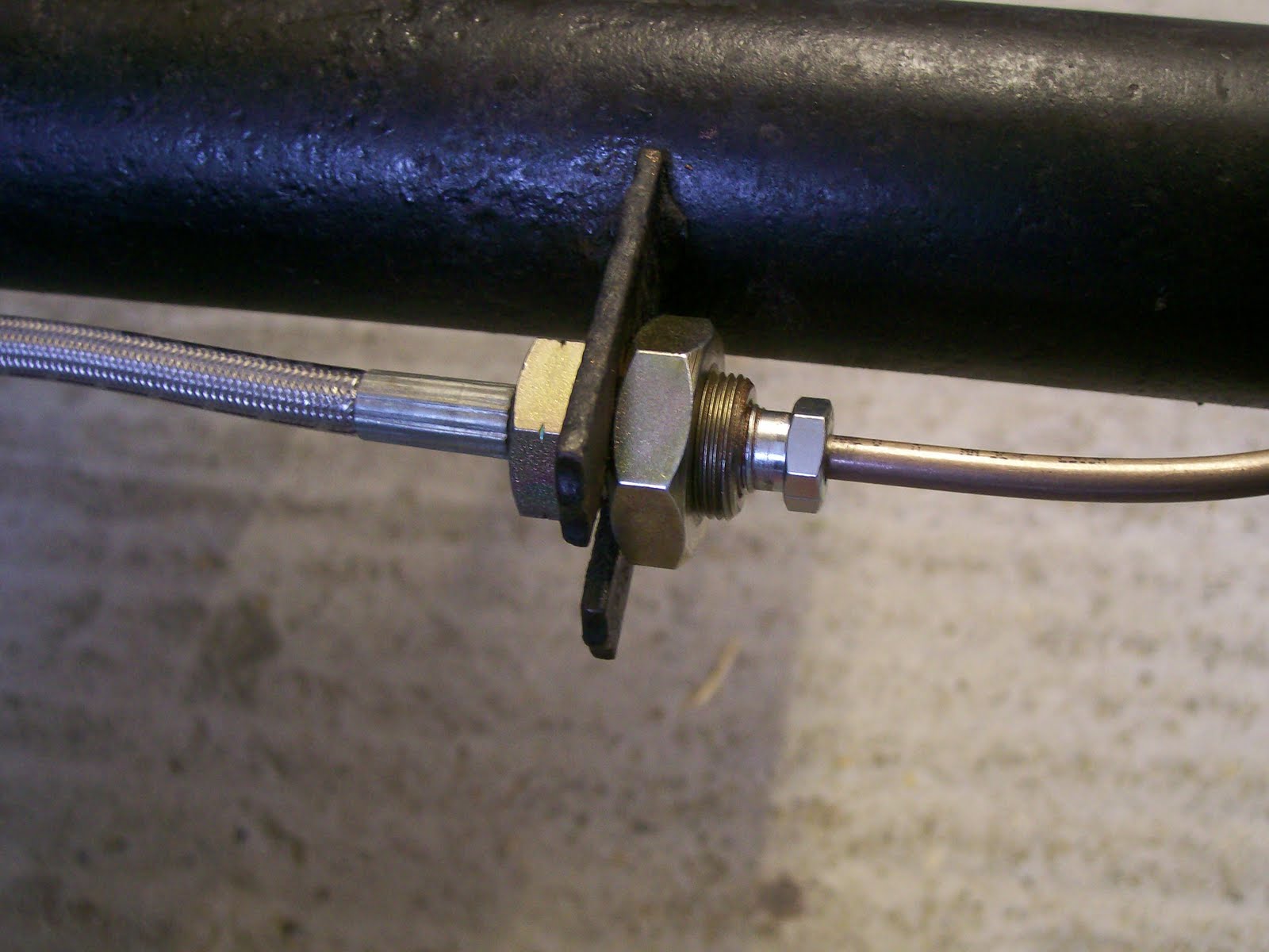
There it meets a T connector.


The top connection is from the passenger side brake. The left extends to the drivers side brake. The right connector goes forward to the master cylinder.


The brake line going forwards where it goes through, along the floor, on the inside.


As you can see the brake line follows the side of the tunnel. On the other side of the tunnel was where it usually runs, being a left hand floor, and there are clips to hold it in place. These need to be added on this side.


The opposite view, looking back.


The line bending with the shape of the floor as much as possible.


At the front it must bend around under where the pedal cluster goes and through the wall again.


Before the line is bent into place.


The line bent into shape and connected to the master cylinder.


The brake reservoir attached.
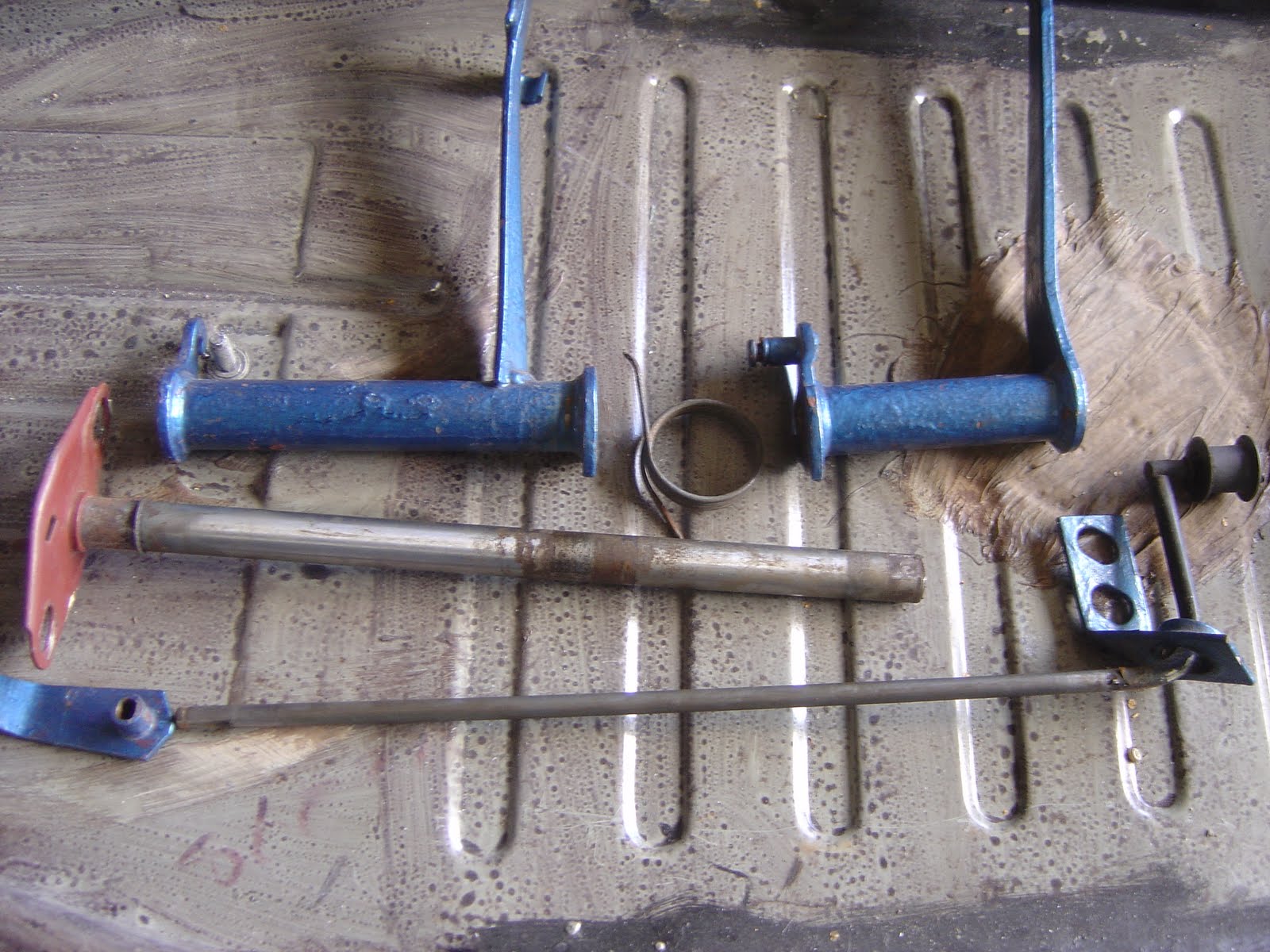
Adding the front brake cylinders

Having previously cleaned the brakes, I had removed the cylinders.


I refitted the brake adjusters taking care to ensure the groove meets the shoe correctly (they slope inwards).


The brake cylinder was cleaned and replaced.


A small amount of grease was placed on the protrusion, on the rear on the brake drum, to allow easy movement and prevent squeaking.


A close up of the spring and retaining washer that hold the shoes inplace.


The assembled brake components, including springs, ready for the brake drum.

Saturday, 11 September 2010

Fitting the brake hoses and pipes

I have fitted goodridge stainless steel hoses front and back.


The brake hoses clips where not required as the hoses had a bolt and nut that secured them.


The rear brake line, copper nickel, should not be susceptible to rust. I bent them by hand and with care.


The brake line, before it is bent, comes straight out of the rear brake cylinder.


The brake line connected to the hose.

New brake cylinders (rear)

The brake drum has a 36mm castle nut the is held on with a split pin. This has been removed along with the adjuster bolts, brake pads and retaining springs/ washers.


I just placed the brake ajuster bolts in the bottle, filled it with white spirit and shook away the grease. After a few minutes of soaking and shaking, I wiped with a rag.


Didn't do much to the brake pads. They look like they have a few more miles left in them so they are going back on. I'm sure these brake pads aren't made of asbestos anymore but I'm not sure if they are contaminated with p[revious brake pad dust.


The adjuster bolts, cleaned greased inside and back in place.


I put the springs on the brake pads and located the tops into the cylinders first. Then I stretched the lower parts into the adjusters. Note the adjusters have an angled edge in the recess where the brake shoe sits. They need to be mated up or the drum will be tight to get on.